A frequently posed question when designing flat roofs is “What upstand height do I need?”
On the face of it a simple question with, one may think, a simple answer. Most of the time the simple answer is “150mm above the finished roof level”. We may give that advice but unless we probe further can we be sure that the advice is fully understood and correctly interpreted? In our experience, not always.
BS 6229:2003 ‘Flat roofs with continuously supported coverings Code of Practice’ and BS 8217:2005 ‘Reinforced bitumen membranes for roofing Code of Practice’ both state that if unwanted water ingress into the building is to be avoided all weatherproofing upstands occurring around the roof area; (which would include abutments, rooflights and service vents etc) must have a minimum height of 150mm.
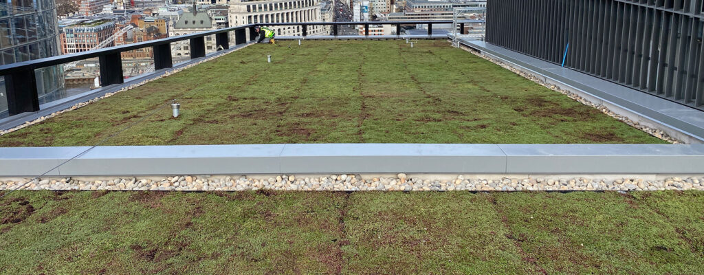
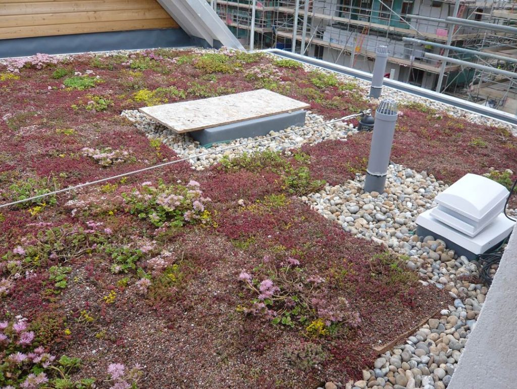
This dimension should be measured from the finished surface of the roof, which would include anything laid over the waterproofing such as pedestrian walkway systems or any “Bio-diverse” system using the roof as a base.
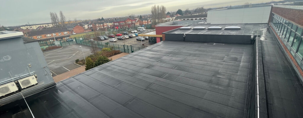
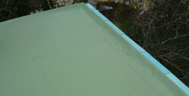
On exposed membrane roofs the upstand height is measured directly from the membrane surface.
Rainwater can build up on a roof during heavy storm events and it may be stating the obvious, but unless checked this water could spill into building and saturate construction elements, electrical installations as well as internal finishes and effects.
The upstand will prevent surface water running into the building, in addition, heavy rain can also splash above the surface and that 150mm minimum requirement can protect against ingress issues caused by such an event.
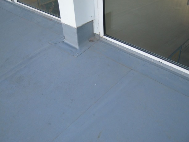
It is also vitally important to ensure the correct sequencing is followed to ensure the flow of water naturally bypasses the upstand interface. Upstands should be taken behind vertical surfaces, such as cladding, or a proprietary cover flashing should be employed.
What happens if I do not achieve these minimum requirements?
If your design cannot accommodate the required upstand height, you run the risk of falling foul of the local authority building control or third party insurers. If they don’t sign off the waterproofing there can be issue obtaining mortgages, for example.
If neither of the two previously mentioned bodies are involved it would be likely that whoever is offering the waterproofing warranty would exclude any such detail in the event that an ingress problem arose that was attributable to non-conforming details.
Could I amend the waterproofing to help solve this issue?
On occasions, where upstand heights are minimal, and where practical, a box gutter section or “step down” has been introduced to accommodate the upstand height and mostly this practice has been deemed a suitable solution, however, this may not be how the standards should be interpreted as they indicate that the upstand should be measured from the main roof level. This also applies to purposely designed box gutter sections in a similar position.
Product selection can have an impact on detail design and performance. Less thermally efficient insulation will increase the roofing system height, therefore, choosing (as examples) P.I.R. foam over Mineral Wool or Expanded Polystyrene will help reduce the overall thickness.
The reasons for choosing mineral wool may be for specific requirements or performance so it is important to understand the full impact of substituting various products.
Even the choice of different faced P.I.R insulation can have an impact. Aluminium faced insulation generally has a lower “K” Value (Thermal Conductivity figure) than Tissue faced boards, therefore, to achieve a typical U Value of 0.18 W/m²K (R Value 5.30) you may achieve it with 20mm less Aluminium faced than Tissue faced.
An option that is becoming more and more common is to include or allow for insulation to be introduced into the roof cavity.
Typically around a third of the thickness can be housed within the roof void but it is vital that a condensation risk is carried out to ensure there is no inherent risk of condensation occurring within the build-up. The insulation would normally sandwich the deck as opposed how it would be installed in a cold roof construction.
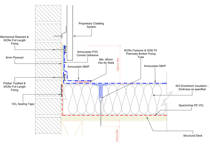
Correct sequencing to ensure the waterproofing is protected by higher placed elements of the construction.
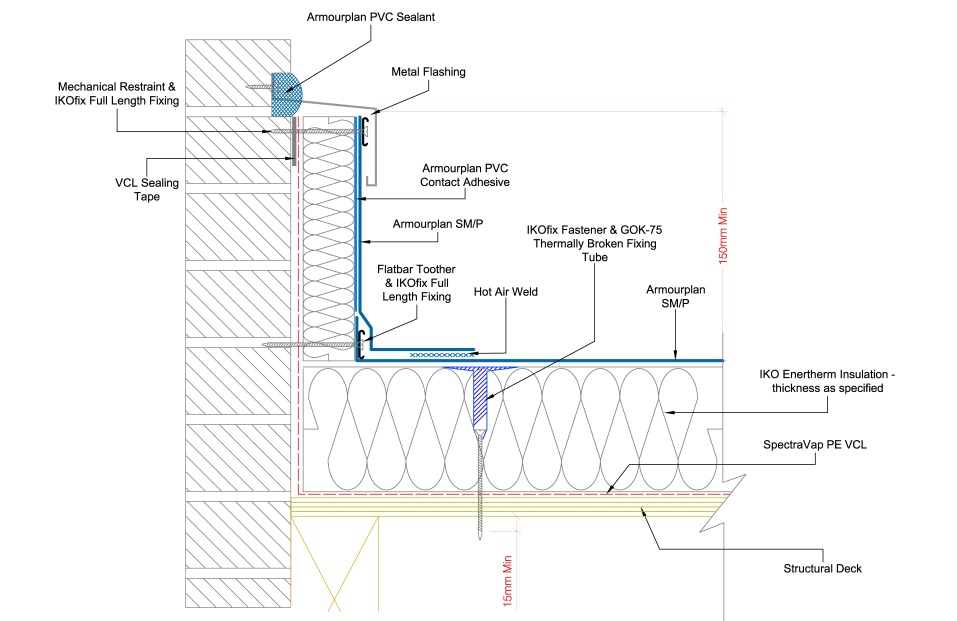
Typical upstand to brickwork.
There are also occasions when the 150mm rule does not apply…
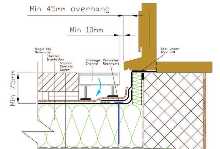
Door thresholds
In recent times there has been a notable exclusion to the 150mm rule, this being an agreement supported by The NHBC & SPRA (amongst others) that at door thresholds.
The requirement has been reduced to 75mm at the opening, provided that the following conditions are met:
- Rapid removal or rainwater across the width of the opening, by including a proprietary drainage channel in front.
- The waterproof membrane extends 150mm height in the door reveal and roof/abutment wall.
- The waterproof membrane flashing extends fully below the door frame bottom rail and is sealed to.
- A horizontal gap of minimum 10mm between frame front edge and drainage.
Warm roof – principles.
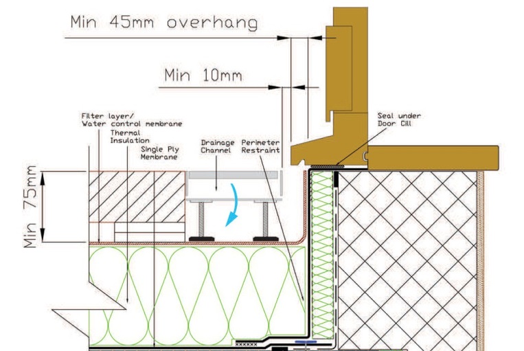
Inverted roof – principles.
In cases where disabled or wheelchair access is required, this is best achieved by constructing ramps, preferably with a porous or perforated surface, which not only allows rainwater to drain through, but provides a surface with grip.
What about “open” elevations?
Unless the elevation is an eaves detail providing drainage it is always good practice to provide a check kerb to deflect the water and prevent it spilling over the side. As well as being inconvenient to anyone passing by the water could saturate and affect walls, doors and windows or any finishes.
Check kerbs should be high enough to function and typically they should be at least 50mm, but good practice sees them typically at 75mm.
Check kerbs should be dressed to weather the external face of the kerb as well as any construction joints immediately beneath.
Example of a simple check kerb detail.
Refurbishment
Building designers of the past may never have had the foresight to consider how drastically building design would change in terms of thermal performance and energy conservation.
There are still many buildings out there with low and clerestory windows all but sitting on the roof surface. How can we deal with this?
Not like this!
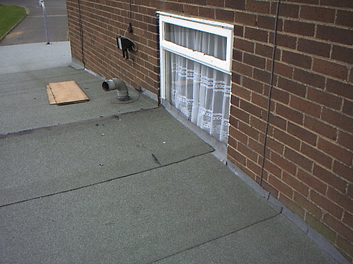
The only real solution with such a problem is to remove the windows and replace them with ones of a lesser dimension, or if possible, reposition them at a higher level.
In the above instance the client accepted an exclusion in the guarantee.
In conclusion: seek advice
Much of the art of having a successful flat roof installation is ensuring it is designed in accordance with the relevant standards, accepted good practice and manufactures guidelines. Thankfully, an awful lot of designers do seek advice.
There is a lot of experience in the flat roofing industry and most, if not all, industry bodies and manufacturers will have dealt with these issues before. Again most, if not all, will be happy to share their experiences and provide meaningful advice.
We, here at IKO Polymeric, are more than happy to help and advise.
Frank Williamson F.I.o.R.
Technical Manager, IKO Polymeric.
Acknowledgments
NHBC Standards 2016 Chapter 7.1 Flat Roofs and Balconies
SPRA – Single Ply Roofing Association Design Guide
Original article was posted on SIG Design & Technology
For more information, please contact IKO Polymeric’s Technical Team.
Phone: 01257 488 012
Email: polymeric.technical.uk@iko.com